Customising
AUTOFLUG provides a wide range of Fuel Gauge Transmitters. AUTOFLUG Fuel Gauge Transmitters are based on company standardised components such as tubes, flanges, level sensors, electronics, cables and connectors.
In short time AUTOFLUG can configure, build, test and qualify sensor prototypes. Series production can start immediately thereafter. AUTOFLUG performs fuel tank studies based on customer supplied CAD data in order to define the optimum quantity and position of Fuel Gauge Transmitters and the associated height vs. volume tables for fuel volume and fuel mass calculation.
A Fuel Compensator can be integrated into the Fuel Quantity Measurement System to improve accuracy by compensation for different fuel types and fuel temperatures.
Fuel Gauge Transmitter Functionality
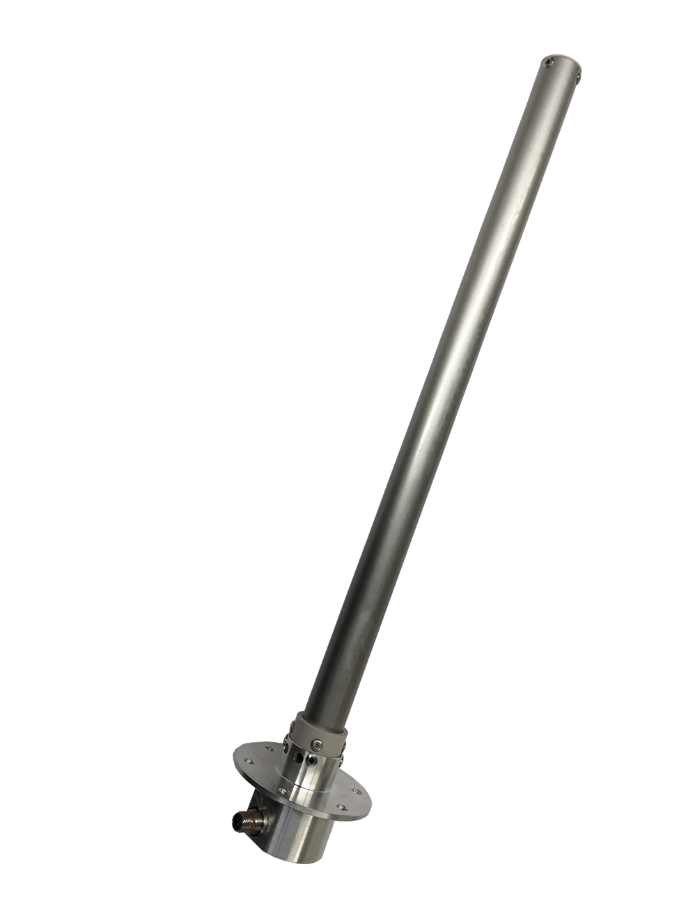
The Fuel Gauge Transmitter family CERTIFLY is a flange mounted Fuel Gauge Transmitter (FGT) designed for aircraft fuel gauging application in main fuel tanks and auxiliary fuel tanks.
The sensor length is adaptable according to customer requirements. The sensor fuel height measurement output signal options comprise: PWM, Frequency, CAN, Current and Voltage.
The flange mounted sensor is a linear active capacitance type sensor. The capacitor’s conductive surfaces are provided by straight concentric tubes. The measured capacitance is dependent on the fuel height at the sensor. The sensor electronics transforms the measured capacitance which represents the actual fuel height into an electrical output signal (see options above).
Features & Options
Mechanical Interface |
|
| Mounting | flange mounted from top or bottom (no directional limitations) |
| Flange Diameter | E.g. Angled 6-hole mounting flange with a hole circle of 60 mm (2.36 in) (limited to 32-33 mm) |
| Sensing length | 100 mm to 1,000 mm (3.94 in to 39.4 in), measured from flange mounting plate to the end of the sensing element |
Electrical Output Signal Options |
|
| “CAN” | The FGT provides the measured fuel height as a CAN output signal (DAL C) with following output parameters: CAN 2.0B (Extended Frame Format) Bit rate 125 kbps |
| “Current” | The FGT provides the measured fuel height as a current output signal with following output parameters: 4 to 20 mA |
| “Voltage” | The FGT provides the measured fuel height as a voltage output signal |
| “PWM” | The FGT provides the measured fuel height as a PWM Pulse Width Modulated output signal with following parameters: Frequency: 488 ± 2 Hz Amplitude: < 1 V equals “LOW” and > 4 V equals “HIGH” Max. signal current 1 mA |
| “Frequency” | The FGT provides the measured fuel height as a CTS (frequency) output signal with following parameters: T = 100 µs ± 0.25 % “dry” Amplitude: 5 VDC ± 1 VDC (o.c.) |
Accuracy |
±0.8% of the measurement range at empty condition (dry) and shall be within the linear increasing tolerance up to ±2.5% of the fuel-specific measurement range at full condition (fully immersed) |
Weight |
180 g + 200 g/m (0.40 lb + 0.011 lbs/in) |
Electrical Interface |
|
| Connector | Series 800 “Mighty Mouse” part number 800-012-07 M6-7PN |
| Input Power | 15.0 VDC ± 2.0 VDC, maximum voltage ripple 60 mVpp, max. 25 mA |
Temperature Range |
|
| Temperature & Altitude | in accordance to SAE AS405D |
| Temperature Variation | in accordance to SAE AS405D |
Applicable Fluids |
|
| FAME contamination | The FGT shall be applicable for following fuel types with a potential FAME contamination limit of up to 100 ppm |
| Fuel Types | JET A-1, JP-8, F-34/F-35 JET A, JET B, JP-5, F-44 JP-4, F-40 EN 590, F-54, DF-2 JP-8+100 |
Environmental Qualification |
|
| SAE AS405D | Fuel and Oil Quantity Instruments |
| RTCA/DO-160G EUROCAE ED-14G |
Environmental Conditions and Test Procedures for Airborne Equipment |
| RTCA/DO-178C EUROCAE ED-12C |
Software Considerations in Airborne Systems and Equipment Certification |
| RTCA/DO-254 EUROCAE ED-80 (Issued 4-19-00) |
Design Assurance Guidance for Airborne Electronic Hardware |
| FAA AC 25.981-1C | Fuel Tank Ignition Source Prevention Guidelines |